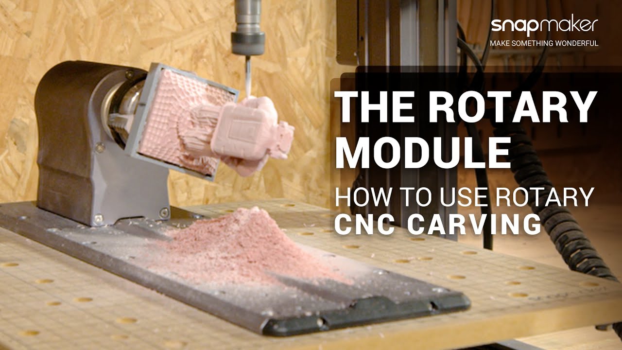
by adding a fourth axis the rotary module realizes more advanced cnc carving and laser engraving on your snapmaker 2.0 machine making it possible to create your projects in a new dimension in this video we will show you how to cnc carve with the rotary module by making a chess piece it will cover five steps including secure material attach cnc bit set work origin generate g-code as well as start carving and remove finished work before we start you need to prepare the following tools and materials a vernier caliper or ruler screwdriver with h 2.5 and h 2.0 bits usb flash drive cnc safety goggles the pair of 14 millimeter and 17 millimeter open-end wrenches er 11 collet er 11 nut calibration card or a piece of a4 paper as well as the straight groove v-bit the chuck wrenches and the cylindrical epoxy tooling board that come with the rotary module make sure the machine is powered off install the cnc carving module and cnc carving platform on the machine following the quick start guide choose the appropriate location on the base to attach the rotary headstock and use four m four by eight hex socket head screws to fix them together from the bottom of the base attach the base along with the rotary headstock to the middle of the cnc carving platform with 10 m4 times 14 hex socket head screws to finish the assembly connect the cable for rotary module to the add-on 2 port on the controller from behind the z-axis the rotary module is equipped with a three-jaw chuck and a tail stock which support materials in various sizes the chuck can do inward and outward clamping the inward clamping is more adaptable to the material shape but diameter of the material should be no more than 60 millimeters outward clamping can be used to secure tubular materials supporting a maximum diameter of 136 millimeters but to use outward clamping do pay attention to the inside diameter of the material which should be between 20 millimeters and 100 millimeters if the material requires a switch to outward clamping use one chuck wrench to hold the chuck and the other to loosen the scroll plate counterclockwise until the jaws can be removed from the channels [Music] then insert the jaws back into the channels clockwise in the order of one two three and turn the chuck clockwise using chuck wrenches till the spiral inside the chuck engages the teeth of the jaws continue to tighten the jaws if the jaws close up together the installation is successful to switch back to inward clamping the insertion sequence of the jaws should be three two one before fixing the material to the chuck you should measure the length and diameter of the material for subsequent use with an accuracy of 0.1 millimeter loosen the chuck put one end of the material onto the three-step jaws and make sure it is coaxial with the chuck turn the scroll plate clockwise to tighten the chuck be careful not to tighten the jaws too much or it may cause damage to the material during cnc carving the tail stock can hold objects securely in place by screwing the hand wheel and the set screw you can adjust the tail stock center to fit the size of the material with the tail stock installed the maximum material length is 70 millimeters for a250 rotary module and 170 millimeters for the a350 one if the material is over length or its length or weight will not affect stability you can go without the tail stock anyway if you need to use the tail stock make sure to install it after the step of set work origin otherwise the cnc carving module will bump into the tail stock in that step the straight groove v-bit features long and sharp carving edges that can penetrate deep into the material and can therefore carve exquisite hollow objects first tilt the er 11 collet into the er11 nut until the collet snaps into place insert the bit into the collet until the bit bottoms against the collet [Music] twist the entire unit onto the shank of the cnc carving module and then tighten the nut using the open end wrenches for four axis cnc carving the work origin is at the center of the material's front surface once the work origin is set the machine knows the xyz and b coordinates of the material and then the position of the carving area [Music] first turn on the machine and upgrade the firmware firmware above version 1.9.0 can be upgraded to version 1.12.0 or above on the touchscreen via wi-fi go to settings select firmware update [Music] check for updates update now tap complete read the safety instructions and walk through [Music] and go to the home screen there are two ways to set work origin you can either use the origin assistant or do it manually before you start carving here we'll introduce the first one tap toolbox origin assistant and type in the material length and diameter measure make sure there is no gap between the jaws and the material in their contact surface and that you haven't installed the tail stock to the base tap next select straight groove v-bit next the tool head will move to near the material follow the instructions to move the bit to the exact position shown on the screen then tap set to confirm the x y z and b coordinates one after another make sure you and any viewers have put on your cnc safety goggles [Music] put the calibration card or a4 paper between the cnc bit and the material move the tool head to where the bit shank slightly touches the top surface of the material you should feel slight resistance when you pull out the card and see it wrinkled when you push it forward tap set x1 and set x2 in the same way [Music] when setting y origin you need to move the shank next to the front of the [Music] material and for z origin it should be the tip that touches the top surface [Music] finally turn the material to a certain degree if needed and tap set b to finish setting work origin [Music] if the cnc bit bumps into the machine when you are setting work origin turn off the machine immediately or press the emergency stop button download the latest snapmaker lube and from snapmaker's official website to upgrade it to version 3.14.0 or above open the software and go to cnc g-code generator select 4-axis and job type and input the material length and diameter go to the case library find the test file and click load or upload a model file in stl format [Music] the canvas in the software represents the side spread area of the cylindrical material within which you should put your model and adjusted size orientation in position note that the highlighted part represents the actual clamping area of the jaws to avoid the tool head bumping into the jaws do not place your model beyond that area use the default parameters in configurations and click process select straight group vbit under carving tool and again use the default parameters in configurations tick auto tool path preview to check the carving path and click simulate to preview the finished work [Music] click generate g-code and export g-code to file to save the g-code file to your usb drive insert your drive into the controller tap start on the home screen or select file in the app list screen and tap usb to open the gcode file in your drive preview the file and tap ready [Music] again make sure you and any viewers have put on your cnc safety goggles and tap next as we've already set the work origin through origin assistant here we don't need to set it again manually so swipe left on the touch screen and tap run boundary to preview the work area if the work area is not ideal adjust y or b offset to reset the corresponding origins and run boundary again if you need to use the tail stock you can now choose the appropriate location on the base to install it and tighten it with two m4 by 10 hex socket head screws then use the h 2.0 screwdriver bit to loosen the set screw on the tail stock center and turn the hand wheel to adjust the length of the center until it presses against the central point of the material's front surface adjust the tail stock center to align the groove on it with the set screw and tighten the set screw now tap start to begin carving when you finish clean the dust with a vacuum unscrew the er11 nut along with a bit remove the tail stock use the chuck wrenches to loosen the chuck and remove the finished work that's all for this video for laser engraving with the rotary module please continue to watch our video tutorial how to use laser function with rotary module thank you for watching


